
The basic operating principle
Seen from the outside, a cable car looks like nothing more than “a rope hanging in the air with cabins attached to it”. A working installation, however, stands up only because a drive unit, a continuously monitored rope tension, mechanisms that clamp the carrier to the rope, sheave assemblies arranged along the line and a safety circuit watching over all of them work together.
In aerial ropeways, movement is transmitted through a steel rope circulating on a closed loop. At one end of the rope is the drive station, at the other the return station — which is usually also the tensioning station. As the drive bullwheel turns, the friction between the bullwheel surface and the rope moves the rope, and the carriers attached to it travel along the line with it.
The critical point is this: movement is transmitted not by a toothed engagement but by friction. This is why the tension of the rope on the bullwheel is a design quantity the installation cannot work without. If tension falls, the rope slips on the bullwheel; if it rises too far, the rope, the sheaves and the structural members are pushed beyond their design limits.
What separates the system families from one another is how this basic principle is arranged: monocable systems in which a single rope both carries and hauls; bicable and tricable systems in which carrying and hauling are given to separate ropes; and the aerial tramway and funicular layouts in which two vehicles balance each other. The detail of these distinctions is covered separately in the guide to cable car and ropeway types.
The drive station
The drive station is where the installation turns energy into movement. A typical arrangement contains the following elements.
Main motor. In today’s installations, speed is controlled by an electric motor that can be adjusted continuously through a frequency converter. This allows starting and stopping to be gradual, and line speed to be reduced according to wind or passenger volumes.
Gearbox. It converts the high speed of the motor into the low speed and high torque the drive bullwheel needs. Gearbox oil temperature, pressure and level are among the quantities monitored during operation.
Drive bullwheel. This is the large wheel the rope turns around; its surface carries a lining that seats the rope and increases friction. The bullwheel also carries a backstop, which prevents the installation from running back when loaded.
Auxiliary (emergency) drive. This is an independent drive used to bring the carriers into the station when the main drive or the mains supply is out of service. The common solution is a diesel-hydraulic unit with its own fuel and energy source. The auxiliary drive runs at low speed, and its purpose is not to continue operating but to clear the line. For scenarios in which even this drive cannot be started, rope evacuation procedures are defined separately; EN 1909 governs this area.
The drive unit is not located in the bottom station at every installation. Depending on the line profile, the power infrastructure and the station architecture, the drive may also be placed in the top station or in an intermediate station.
The tensioning system
Rope tension is not a fixed number: rope length changes with temperature, passenger load is distributed differently along different sections of the line, and the rope stretches somewhat over its service life. The tensioning system continuously balances these variations and keeps tension within the design range. Two basic solutions are used.
- Counterweight. The carriage carrying the return bullwheel is connected to a concrete or metal weight through a rope-and-sheave arrangement. The weight moves freely in the vertical direction and holds the tension physically constant. It is simple and works independently of the power supply; on the other hand, it requires considerable vertical space inside the station.
- Hydraulic tensioning. The return bullwheel carriage is connected to cylinders whose pressure is controlled by a hydraulic power unit. Tension can be measured directly as pressure, recorded, and linked to the safety circuit through lower and upper thresholds. Because it is compact, it is preferred in urban and confined stations.
In both solutions the travel of the carriage is limited; as the carriage approaches its end positions, first a warning and then a stop signal is generated. A counterweight setting down, or hydraulic pressure moving outside its thresholds, are among the conditions that require the installation to be stopped.
Rope configuration
In a ropeway, the “rope” is not a single element but an arrangement divided according to defined duties.
- Carrying-hauling rope. In monocable systems a single rope both carries the weight of the carriers and moves them. Most gondolas and chairlifts use this arrangement.
- Track rope plus haul rope. In bicable systems a fixed, tensioned track rope acts as a “rail”; the vehicle runs along this rope on a wheeled carriage, and a separate haul rope moves the vehicle back and forth. This is the classic arrangement of aerial tramways.
- Tricable (3S) arrangement. Two parallel track ropes and one haul rope are used. The wide track width and the high track rope tension make this the most wind-resistant family of aerial ropeways. Wind resistance generally starts with the monocable gondola, passes through Funifor and aerial tramway designs, and reaches its highest level with the 3S.
- Auxiliary ropes. Elements such as a rescue rope, a tensioning rope and, in some layouts, a balance rope are added depending on the installation.
The construction of ropes, their inspection and their magnetic non-destructive testing form a subject in their own right; the article on ropeway wire ropes goes into that detail.
Grips: how the carrier is attached to the rope
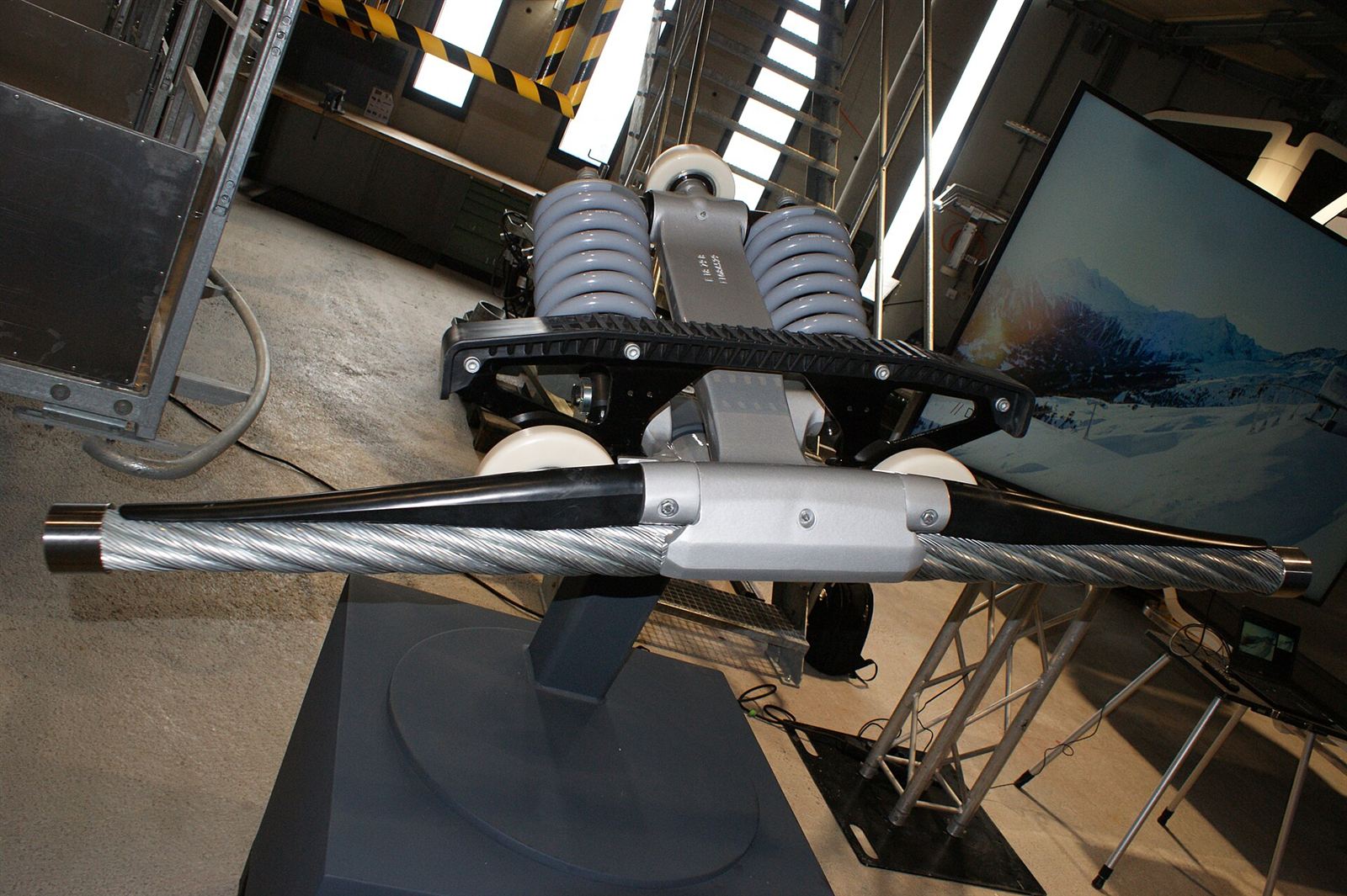
The grip is the mechanism that clamps the carrier onto the rope, and it largely determines the character of a ropeway.
Fixed grip
The carrier is permanently attached to the rope. The force produced by the spring pack presses the jaws onto the rope continuously. The construction is simple and the maintenance burden low; on the other hand, because the carrier also moves at line speed through the station, boarding and alighting take place at that speed. Line speed is therefore limited: on a four-seat fixed-grip chairlift the typical value is around 2.3 m/s, and it falls as chair capacity increases.
On fixed-grip installations the position of the grip on the rope is shifted periodically. This both prevents the grip from fatiguing the rope at the same point and makes visual inspection of that section possible.
Detachable grip
The carrier releases the rope at the station entrance. The sequence is as follows: the grip-opening rail opens the jaws, the carrier is taken onto the guide rail inside the station, a series of rubber-tyred conveyor wheels slows it down progressively, it moves through the boarding zone at a low speed of roughly 0.8–1.2 m/s, at the exit it is accelerated again up to rope speed, and the closing rail clamps the grip onto the rope.
What this arrangement delivers is capacity, directly: line speed can rise to 6 m/s while boarding still happens at walking pace. The price is far more complex station mechanics and a more intensive maintenance programme.
The detachable grip is also a component monitored closely from a safety point of view. Before launch, checks confirm that the grip has genuinely closed, that the geometric position of the jaw on the rope is correct, and that the gripping force is at its design value. The relevant clause of EN 13796-1:2017 requires the geometric positions of the rope and the jaws to be monitored and the detachment of grips to be supervised. On gripping-force measuring devices the typical acceptance range is of the order of ±10% of the nominal value.
Line equipment
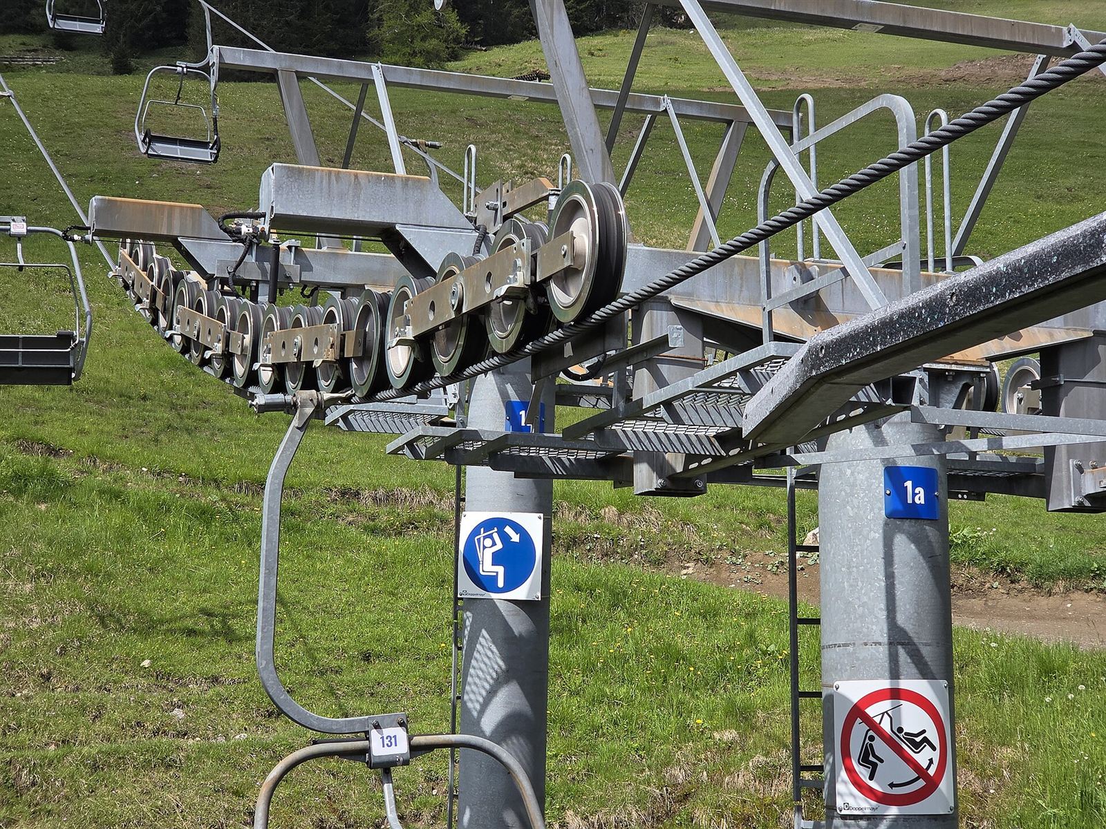
Towers
Towers hold the rope on the intended profile and maintain the vehicle’s safe clearance from the ground and from obstacles. They are mostly tubular steel structures; lattice construction is used for very large spans. Tower height and position are determined by the line calculation: rope sag in each span, the carrier swing envelope, and wind and icing loads all enter the calculation. Towers also carry escape and access ladders, rescue platforms, lighting and line monitoring equipment.
Sheave assemblies
The rope does not run over a single sheave on a tower but over a sheave assembly. The assembly is a hierarchy formed by mounting sheaves in pairs on balance arms (rockers), and those arms in turn on higher-level arms. The aim is to distribute the rope load over the sheaves as evenly as possible and to soften the impact created as a carrier passes.
There are three types according to position:
| Type | Function |
|---|---|
| Support assembly | Supports the rope from below; the rope passes over the tower |
| Hold-down assembly | Presses the rope from above; used on sections where the rope pushes the tower upwards |
| Combination assembly | Performs both supporting and hold-down duties on the same tower |
Sheave assemblies carry the densest concentration of safety equipment on the line. A derailment switch — detecting the rope leaving its sheave groove — is fitted on the entry side of the assembly; when the number of sheaves exceeds a certain threshold, one is added on the exit side as well. These switches are expected to trigger at the moment of derailment and not to be resettable. Alongside the sheaves there are rope catchers that hold a rope which has come out. EN 13223 requires that, if a sheave seizes or is missing, or if the rope leaves the sheaves onto a rope catcher, the movement of the balance arms is limited so as to allow the grip to pass.
On more recent installations, rope position detection (RPD) systems that continuously measure the position of the rope inside the sheave groove have been added alongside these mechanical switches. They give warning not after a derailment has happened, but when the rope begins to slip out of the groove.
Station equipment
The station is where the passenger comes into contact with the system and where the carrier is maintained. The typical equipment is as follows: the boarding and alighting platform and the passenger guidance layout; on detachable systems the guide rail and the conveyor line; the garage rail and storage area where carriers are taken off the line; maintenance and inspection rails; the control cabin and operator panels; the intercom and public address system in the cabins.
On urban and tourist installations, step-free accessible access, automatic platform doors and integration with ticketing systems are added to this. In that respect a well-designed station is a component of operational safety as much as of the passenger experience: a significant proportion of incidents arising from misdirection, falls and trapping occurs in the station area.
Brakes
A ropeway has at least two brake systems independent of each other.
Service brake. It acts on the drive shaft next to the main drive, ahead of the gearbox. This is the brake used for normal stops and for controlled emergency stops. Because it works on the high-speed side, a comparatively small torque is sufficient.
Emergency (safety) brake. It acts directly on the drive bullwheel. This means that a failure in the power transmission line — a gearbox, coupling or shaft breakage, for example — cannot disable braking.
For both brakes the common solution is an arrangement closed by spring force and held open by hydraulic pressure: when power or hydraulic pressure is lost, the brake engages by itself. How hard the braking will be is not left to chance either; deceleration is kept within a range that will not throw passengers out of their seats or cause excessive swinging of the carriers. Brakes are verified periodically by loaded brake tests.
On funiculars and surface lifts, elements specific to the system type are added to this scheme: on funiculars, mechanical brakes on the vehicle acting on the rail; on surface lifts, separate devices against rope breakage or overspeed.
Safety circuits and line monitoring
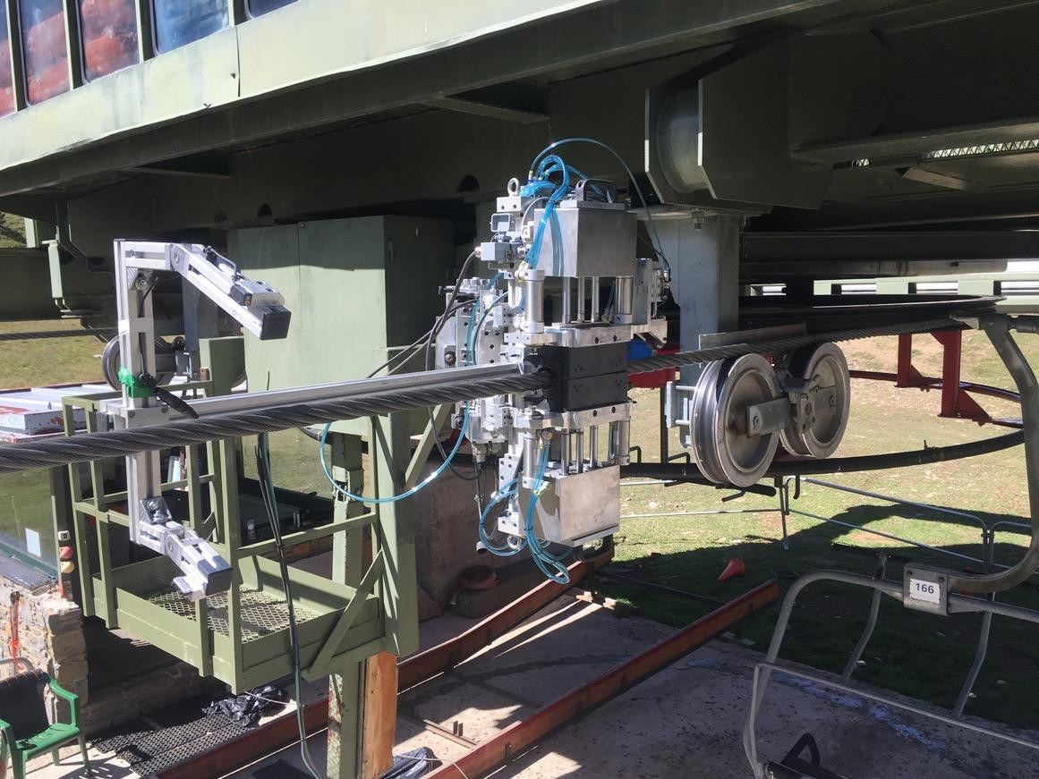
All the sensors listed above meet at a single point: the safety circuit. This circuit works on closed-loop logic; the opening of any switch on the circuit does not mean that a signal is awaited but that the signal is interrupted, and the installation stops. A broken cable or a loss of supply produces the same result.
The quantities typically connected to the circuit are:
- Derailment switches and rope position detection signals
- Rope tension (hydraulic pressure thresholds) and tensioning carriage end positions
- Rope slip measurement on the bullwheel
- Line speed, overspeed and rollback monitoring
- Grip opening and closing checks and carrier spacing monitoring
- Station entry and exit position switches, platform emergency stop buttons
- Anemometer thresholds
Wind management is a subject of its own within this list. Installations generally work with two thresholds: at the first, line speed is reduced; at the second, operation is stopped. Many operators define thresholds such as slowing down at around 60 km/h and stopping at around 70 km/h; the values vary with the location of the installation, the vehicle type and the line geometry. This is accompanied by designing cabins and chairs so as to reduce wind load, by swing dampers, wind screens and line cameras.
The most instructive aspect of these circuits in the field is this: when an installation stops, fault-finding usually begins not with the mechanics but with the log listing that shows which contact opened. Modern control systems record the state of every channel at the moment of the stop with a time stamp.
What holds the whole together
In a ropeway, no single component is safe on its own. The tensioning system holds the rope’s tension, the safety circuit monitors that tension, the sheave assemblies and rope catchers keep the rope in place, the derailment switches supervise that, two independent brakes guarantee that the drive stops, and the auxiliary drive and the rescue plan cover the case where the drive does not run at all. Each layer is designed on the assumption that another will fail.
The regulatory side of this layered structure is a separate subject: design and manufacture are defined by a family of standards such as EN 12929-1, EN 12930, EN 13223, EN 13796-1 and EN 12927, while commissioning and periodic inspection are defined by EN 1709. In Türkiye the system runs through the Cableway Installations Regulation, which transposes Regulation (EU) 2016/424. For the detail of this framework see cable car safety and EN standards, and for the lifetime maintenance regime of the components and evacuation scenarios see cable car maintenance and rescue. Short definitions of the terms used in this text are collected under the cable car glossary.