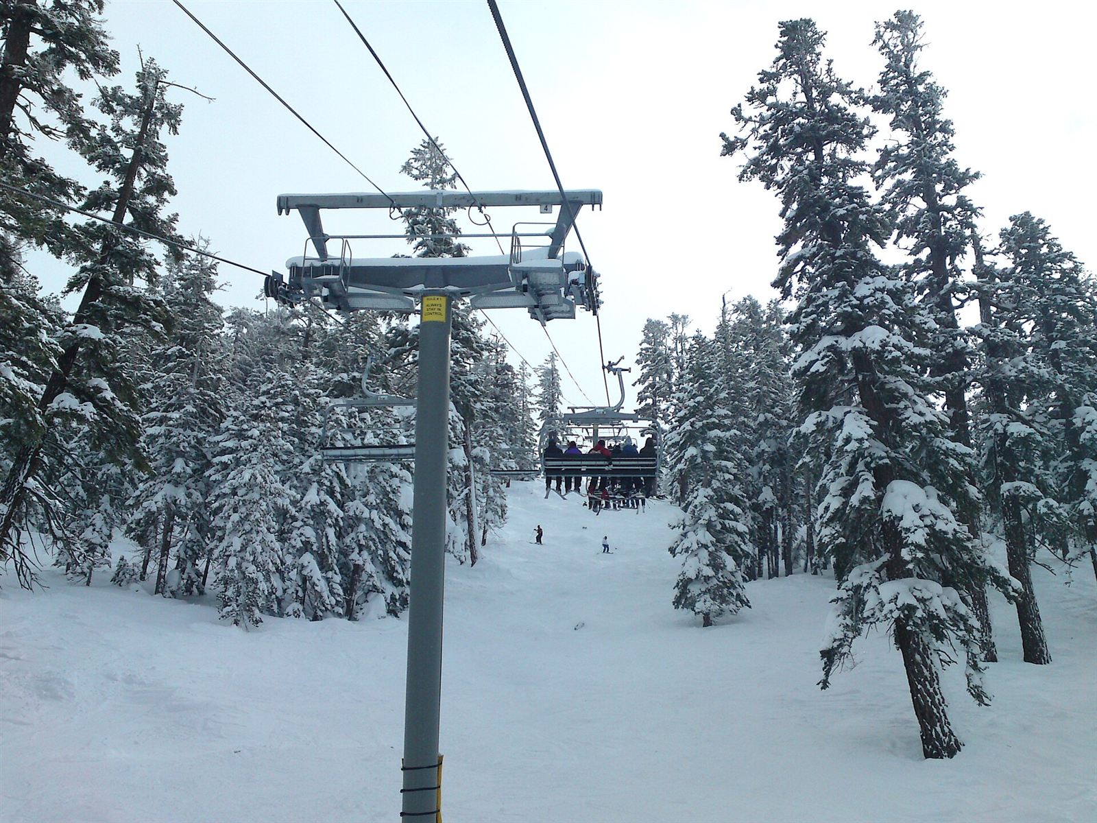
In everyday speech, “cable car” conjures up a cabin hanging in the air. In the technical literature the word covers a far wider family: every transport system whose movement comes from a steel wire rope. That family includes the surface lift on a ski slope, a 3S cabin carrying dozens of people and integrated with the metro in a city centre, and an underground funicular that has run between Karaköy and Beyoğlu since 1875.
This guide takes ropeway systems together with the logic used to classify them: how each type works, its typical capacity range, the conditions under which it is preferred, and where it reaches its limits.
The four axes of classification
Ropeway systems are not separated by a single criterion but by four intersecting questions.
1. Where does the carrier move? If it hangs in the air, it is an aerial ropeway; if it runs on a rail or guideway on the ground, it belongs to the ground-based systems (funicular, cable-propelled automated transport, inclined lift).
2. How many jobs does the rope do? In monocable systems a single rope both carries and hauls. In bicable and tricable systems the jobs are separated: a tensioned track rope carries the load and a separate haul rope provides the movement. The construction and inspection of ropes is a subject in its own right; for the detail, see the article on ropeway wire ropes.
3. What is the movement regime? In continuously circulating systems the vehicles travel without interruption around a closed circuit. In reversible (to-and-fro) systems two vehicles work like a shuttle: one goes up while the other comes down.
4. How is the vehicle attached to the rope? In fixed-grip systems the vehicle is permanently clamped to the rope; rope speed is limited to whatever boarding and alighting comfort allows. In detachable-grip systems the vehicle detaches from the rope as it enters the station, slows down, takes on passengers at low speed and accelerates back onto the line. How the grip, the drive and the safety chain work is set out in detail in how cable cars work.
Aerial ropeway systems
Surface lift (drag lift)
The passenger is not lifted into the air; standing on their skis, they are drawn uphill along a prepared track on the ground. The main sub-types are: the rope tow used on nursery slopes, the T-bar that draws two people side by side, and the single-person platter or button lift.
In terms of investment and structural footprint it is the lightest member of the family; it is economical over short distances and in beginner areas. Typical capacity is in the band of a few hundred to a thousand persons per hour. Against that, it carries only skiers and snowboarders, is closed to pedestrian use and requires a prepared snow surface. The world’s first ski tow was built in Germany in 1908.
Chairlift — fixed grip
The open chairs are permanently attached to the rope. Rope speed is limited by the passenger’s ability to board a moving chair. The system is mechanically simple, its maintenance burden is low and its investment cost moderate; with 2- to 4-seat chairs it typically offers a capacity of the order of 1,200–2,400 persons per hour.
Its limit is speed: on long lines the journey time quickly becomes unacceptable. It is also the type that demands attention in safety terms. According to publications by the French supervision authority STRMTG, roughly 70% of accidents occur on chairlifts, predominantly on fixed-grip ones, and two thirds of those accidents stem not from technical failure but from passenger behaviour — most often from loss of balance while boarding or alighting.
Chairlift — detachable grip
Because the grip detaches from the rope in the station, line speed becomes independent of boarding comfort; line speeds of the order of 5–6 m/s can be reached. With 4-, 6- and 8-seat chairs, capacities in the 2,400–4,000 persons per hour band are achieved. The first detachable chairlift was brought into service at Flims in Switzerland in 1945.
Chairs with protective bubbles, heated seats and backrests, and safety bars that close and lock automatically have become widespread in this class. The design of the safety bar is tied to a standard: EN 13796-1 requires the bar to close over the passenger’s head and, for children, the closing handle to be no more than 0.85 m above the seat.
Monocable gondola (MDG)
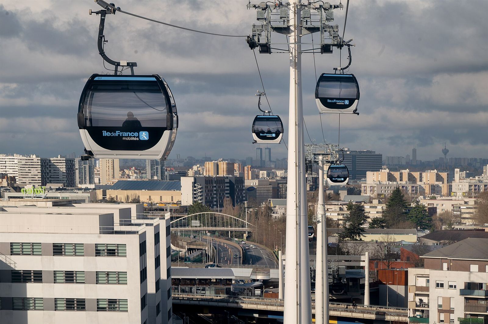
This is an enclosed-cabin, detachable-grip, continuously circulating system. Cabin capacity is typically 6–15 people and system capacity can reach 3,600 persons per hour per direction. Thanks to the enclosed cabin it carries pedestrians, works in all four seasons and is the aerial type best suited to urban use. The first gondola lift was built at Alagna Valsesia in Italy in 1949.
On a typical urban or tourist gondola line, capacities of the order of 2,000–2,500 persons per hour are achieved with 10- to 12-person cabins. Many operators define wind thresholds — for example slowing down at around 60 km/h and stopping at around 70 km/h. The Bursa Uludağ line, for its part, is operated at a capacity of 1,500 persons per hour with a horizontal length of 8,800 m and 156 cabins.
Its limit is wind. A cabin suspended from a single rope is the most exposed of the aerial types to lateral swing.
Bicable solutions: BDG, DMC and Funitel
The first answer to the problem of wind and span is to multiply the ropes.
- BDG (bicable detachable gondola): uses one fixed track rope and one haul rope. The cabin runs on the track rope and the haul rope provides the movement.
- DMC (Double Mono Cable): uses two parallel carrying-hauling ropes; its first application was at Serre Chevalier in France in 1984.
- Funitel: the cabin is suspended from two parallel carrying-hauling ropes, with the gap between the ropes kept wider than the cabin. This wide suspension base largely suppresses lateral swing. The first Funitel entered service at Val Thorens in 1990.
The shared price of this family is more complex station mechanics and higher investment.
3S — tri-cable gondola (TGD)
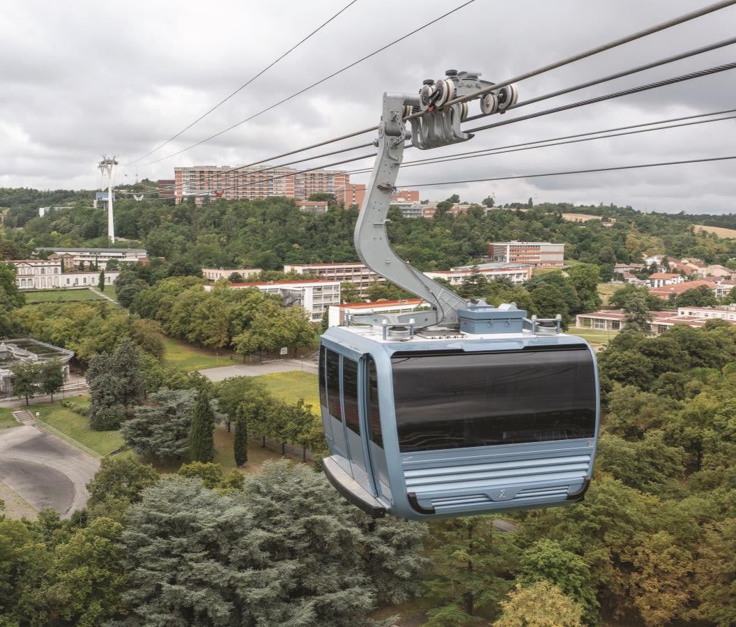
It consists of two fixed track ropes and one haul rope. The cabin runs on the track ropes on rail wheels and is attached to the haul rope by two separate grips. Cabin capacity can exceed 30 people and system capacity can reach 6,000 persons per hour per direction.
The real advantage of the 3S is not capacity but geometry: because very long spans can be built, the number of towers falls, and that becomes decisive in sensitive topography and dense urban fabric. The first 3S was built at the Saas-Fee installation in Switzerland in 1991 (some chronologies give 1990). As an urban example, the 3 km 3S line in Toulouse connects the university and hospital campuses.
The system at the top of OITAF’s wind-resistance ranking is the 3S; the ranking starts with the continuously circulating monocable gondola and rises through the Funifor and the aerial tramway.
Aerial tramway (reversible ropeway)
Usually two large cabins run on one or two fixed track ropes and are fixed to the haul rope. The cabins balance one another: one goes up while the other comes down. Cabin capacity varies from 20 people to over 100, but because it works to a departure interval its hourly capacity is lower than that of gondolas.
Its strength is span. The Zugspitze line carries the extreme values of this class: a single-rope span of 3,213 m, a vertical rise of 1,945 m and a 127 m steel lattice tower. Few towers are a decisive advantage on steep rocky terrain and in protected natural areas.
The first aerial tramway was built on the Bozen–Kohlern line in Italy in 1908. Türkiye’s first cable car, the 1963 Uludağ line, was also a reversible installation working with two cabins of 20 people each.
The Funifor is a variant of this class: the two vehicles work independently of one another, each with its own drive and rope set. Because the ropes run at a wide spacing along the long sides of the cabin, lateral stability is high; in addition, one side can be operated while the other is under maintenance.
Combined installations
Combined systems carrying both chairs and cabins on the same line have also become widespread. Operation can be weighted towards chairs during the ski season and towards cabins in summer or in poor weather.
Ground-based ropeway systems
Funicular
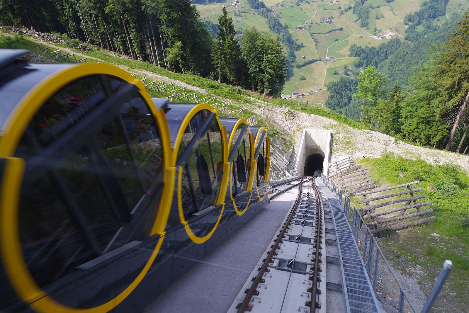
On a steeply inclined rail line, two vehicles are attached to the two ends of a rope passing round the drive bullwheel at the top. The descending vehicle pulls the ascending one. This balance dramatically reduces energy consumption and allows safe operation even on gradients above 100%. The Stoos line in Switzerland, at roughly 48° (of the order of 110%), is the extreme example of this limit, and uses barrel-shaped cabins that stay horizontal along the gradient.
The modern funicular is fully automatic; it can be operated with no staff on board. In terms of station layout it is the cableway system closest to a metro: platform doors, step-free level access and integrated ticketing are applied as a matter of course. Its capacity varies across a wide band according to vehicle size and departure interval.
It is a pioneer historically as well: the first rope-hauled systems to carry people began not in the air but on rails — at Niagara in 1845 and at Lyon in 1862. Türkiye’s own cableway story likewise began underground, with the 573-metre Tünel opened in 1875.
Its legal status is clearly defined. Article 3(9) of Regulation (EU) 2016/424 defines a funicular as a cableway installation in which the carriers are hauled by one or more ropes along a track; the corresponding term in the Turkish Cableway Installations Regulation is “kablolu tren” (cable train). The decisive criterion is not the wheel but the traction: if the movement is provided by a rope, CE marking, an EU Declaration of Conformity and Notified Body assessment are mandatory. Lift legislation and railway safety legislation fall outside the scope. This framework as a whole is examined in cable car safety and EN standards.
Cable-propelled automated people mover (cable APM)
The vehicles run on the ground on their own guideway, but they have no motors: the movement comes from a haul rope embedded in the route. They work fully automatically and driverlessly, monitored from a central control room.
The main areas of use are airport terminal connections and short urban lines. Typical range is up to a few kilometres; capacity varies between roughly 500 and 3,000 persons per hour per direction depending on the configuration, and in some applications speeds of the order of 50 km/h are reached. There are two basic architectures: a shuttle arrangement running back and forth between two ends, and a closed-loop arrangement.
Inclined lift
It is based on a single cabin moving along an inclined path with its own drive and counterweight. It is confused with the funicular, but in regulatory terms it stands in a separate world: it is subject to lift legislation and to the EN 81-22 standard.
The standard also draws the limits of application: the gradient must be between 15° and 75°, the speed up to 4 m/s, and the route straight in the horizontal plane. Typical areas of use are short rises such as buildings, housing complexes, hillsides and shoreline connections.
A good example of how fine the classification can become is the Montmartre line in Paris: it is widely referred to as a funicular, but since the 1991 refurbishment its two cabins have worked independently of one another, with their own traction and counterweight arrangements.
Comparison table
| Type | Rope arrangement | Typical capacity (pph per direction) | Main strength | Main limit |
|---|---|---|---|---|
| Surface lift / drag lift | Single rope, fixed attachment | ~300–1,200 | Lowest investment and structural footprint | Skiers only; carries no pedestrians |
| Fixed-grip chairlift | Single rope, fixed grip | ~1,200–2,400 | Simple construction, low maintenance | Line speed limited by boarding comfort |
| Detachable chairlift | Single rope, detachable grip | ~2,400–4,000 | High line speed, low-speed boarding | Open chair; sensitive to wind |
| Monocable gondola (MDG) | Single rope, detachable grip | up to 3,600 | Enclosed cabin, all four seasons, carries pedestrians | Most wind-sensitive of the aerial types |
| BDG / DMC / Funitel | Two ropes | ~3,000–4,000 | High wind stability | Complex stations, high investment |
| 3S (TGD) | 2 track ropes + 1 haul rope | up to 6,000 | Very long spans, highest wind resistance | Highest investment cost |
| Aerial tramway | 1–2 track ropes + 1 haul rope, fixed attachment | A few hundred – 2,000 | Large cabin, very long spans, few towers | Departure intervals; limited hourly capacity |
| Funicular | On rails, haul rope | Wide range depending on configuration | Very steep gradients, low energy use, metro-like stations | Continuous infrastructure along the route |
| Cable APM | Guideway, embedded haul rope | ~500–3,000 | Fully automatic, driverless | Short to medium distances |
| Inclined lift | Inclined rail, lift drive | Low | Solution at building and hillside scale | Short distance, low capacity |
The values are typical ranges; the real capacity of each installation is determined by vehicle size, line speed and vehicle spacing.
The criteria that govern the choice of type
The most common misconception in the field is to select the system type by looking at capacity alone. In practice the decisive criteria are interwoven:
- Wind regime. A site-specific wind report and the operating experience of nearby installations constrain the choice of type before capacity does. In the French supervision authority’s study, the vehicles most sensitive to wind were determined to be, in order, bubble chairs, cabins and open chairs.
- Span and topography. Where towers cannot be erected — valley, river or protected-area crossings — the 3S and the aerial tramway come to the fore.
- Passenger profile. Skiers only, or pedestrians, pushchairs and wheelchairs as well? This question directly determines the choice between an open chair and an enclosed cabin.
- Operating calendar. A single-season ski operation and a four-season urban line give rise to completely different maintenance and availability requirements.
- Rescue scenario. Can the ground beneath the line be reached by vehicle or on foot? On lines where it cannot, the concept for rescue from the cabin must be worked out at an early stage of design.
- Investment and commissioning time. The fact that urban lines can be commissioned in as little as 1–2 years is one of the main factors making ropeway systems attractive against rail alternatives.
A branch beyond passengers: material transport
The first field of application for ropeway systems was not passengers but materials. That branch is still alive today: cable cranes and material ropeways are used in mining, in the cement industry and on major construction sites. A current example from Türkiye is the high-capacity cable crane arrangements used in the construction of the Yusufeli Dam in Artvin; the concrete for the country’s tallest dam was largely carried by these lines.
For the distribution of installations in Türkiye by type, capacity and operator, see the guide to Türkiye’s cable car and ropeway installations; for short definitions of the technical terms used in this text, see the cable car glossary.
Conclusion
Ropeway systems are not a single technology but a family of solutions that have evolved from a shared principle — taking their movement from a steel wire rope — under different constraints. From the surface lift to the 3S, from the funicular to the cable APM, each type is the answer to a particular combination of gradient, wind, capacity and passenger profile.
Despite this diversity between types, the common ground does not change: all of them are operated under the same regulatory framework, with the same conformity chain and the same regime of periodic inspection. The choice of type is an engineering decision; safety, independently of the type chosen, is an obligation with continuity across the whole life of the installation.