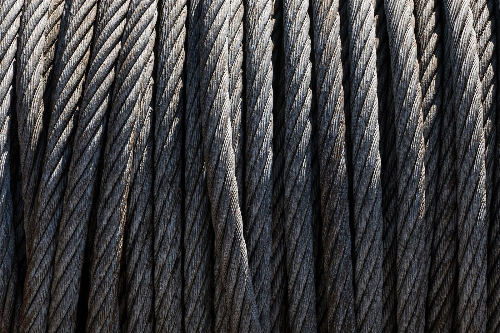
The rope is the one component that cannot be duplicated
In a ropeway installation the drive motor can be backed up, the braking system is multiplied, and the control circuits run over two channels. For the rope there is no such backup. It is the single element that carries the load, transmits the motion and holds the carrier on the line; for that reason the rope is counted among the foremost safety-critical components in the industry.
The steel wire rope itself is older than the ropeway. When Wilhelm Albert produced the first steel wire rope in 1834, the aim was to solve a haulage problem in mines; carrying passengers on aerial lines came onto the agenda decades later. Today in Europe the selection of ropes, their safety factors, discard criteria, storage, transport, installation, splicing, end connections and inspection are all gathered into a single standard: EN 12927:2019. Published in 2019, this standard is the current version, consolidating the eight separate parts of 2004 (EN 12927-1 to -8) into one text. At international level, OITAF’s Commission II is devoted specifically to the properties and inspection of ropes.
For the general operating principle of an installation, see the article on how cable cars work; this article deals only with the rope side of the system.
The construction of a steel wire rope: wire, strand, core
A rope is a three-tier structure, and each tier has a distinct job.
Wire. The smallest unit. It is produced by cold drawing from high-carbon steel; in ropeway ropes it is usually galvanised, because the line stays outdoors for decades, exposed to fog, snow and a salty atmosphere. The breaking strength of the rope is determined by the total metallic cross-sectional area of its wires.
Strand. Layers of wire laid helically around a centre wire form a strand. The strand distributes the load rather than piling it onto a single wire; the failure of one wire affects not the whole rope but the local capacity of that strand.
Core. The central heart around which the strands are laid. There are two basic types: fibre core (natural or synthetic) and steel core. A fibre core provides flexibility and a reservoir of internal lubrication; a steel core gives a higher cross-sectional area, less elongation and better resistance to crushing. In continuously moving haul ropes, the choice of core has a direct effect on fatigue life.
Two geometric properties are added to these three tiers:
- Lay direction: the laying of the strands around the rope axis to the right (Z) or to the left (S).
- Lay length: the axial length required for one strand to complete a full turn around the rope. In inspection, broken wires are always counted per lay length; the lay length is therefore not merely a manufacturing parameter but also a measurement reference.
Internal lubrication (grease) also counts as a structural component: it reduces friction between wires and internal wear, and it forms a barrier against corrosion. A loss of lubrication is a silent degradation mechanism that shortens rope life even while the broken-wire count is still below the limit.
Track rope and haul rope
The most fundamental distinction in ropeway terminology is whether or not the rope moves.
| Property | Track rope | Haul rope |
|---|---|---|
| Movement | Stationary, held under tension | Moves continuously as an endless loop |
| Function | Acts as a rail; the carrier’s sheave assembly rolls on it | Drags the carrier by means of a grip |
| Typical construction | Full-locked spiral rope | 6- or 8-strand rope with a core |
| Ends | Terminated with an anchor block or a tensioning weight | Closed with a long splice, forming an endless loop |
| Loading | Predominantly static; local crushing and wear | Fatigue; repeated bending over bullwheels and sheaves |
The practical consequence of this distinction is that a track rope, by design, cannot pass around a bullwheel. It is rigid and resists bending; indeed that resistance is a desired property. A haul rope, on the contrary, has to be flexible enough to travel around the drive bullwheel and hundreds of sheaves millions of times.
The rope arrangement varies by system family:
- Monocable gondolas and chairlifts: a single rope both carries and hauls.
- Bicable (2S) and aerial tramways: one or two track ropes with a separate haul rope.
- 3S systems: two track ropes and one haul rope. This is the arrangement most resistant to wind.
- Funitel and DMC: two parallel haul ropes; the carrier is suspended from the two ropes with a wide spacing.
- Funicular: a rope hauling rail vehicles, accompanied by balance or safety ropes.
The details of the system types are the subject of a separate article, the guide to cable car and ropeway types.
Beyond these two, an installation contains other ropes as well: tensioning ropes, balance ropes, rescue and lifeline ropes, and on some lines a separate safety rope. All of them are inspected within the framework of the same standard.
Full-locked ropes
Almost all track ropes are full-locked ropes. Their construction differs markedly from the others: at the centre there are several layers of round wires, while in the outer layers Z-shaped wires are laid so as to interlock, in alternating directions in successive layers. The result is a surface with no gaps.
What this geometry delivers:
- A smooth rolling surface. Since the carrier’s sheaves run directly on the rope, every irregularity in the surface turns into vibration and local wear. A full-locked construction keeps that surface flat.
- A high metallic cross-sectional area. More steel at the same nominal diameter, hence a higher carrying capacity and lower elongation.
- Resistance to lateral deformation. The interlocking of the Z wires holds the structure together against crushing and flattening.
- A closed surface. It makes it harder for water and dirt to get in, and retains the internal lubrication for longer.
The first examples of the full-locked construction go back to the 19th century; smooth rope production was achieved in 1884 by Latch & Batchelor, and this type came to be known as “locked coil rope”.
The closed surface also has a price: it limits visual inspection. A wire break beneath the outer layer, or internal corrosion, cannot be detected by looking at the rope. This is precisely why, on full-locked ropes, magnetic inspection is not a preferred method but a mandatory one.
Splicing
The haul rope has to be an endless loop, and that loop is achieved not with clamps, grips or welding, but by reconstructing the rope’s own structure. The method is the long splice.
It works as follows: the two ends of the rope are separated into their strands over a certain length. Opposing strands are unlaid in turn and placed into the vacated groove of the other end; the operation is repeated strand by strand, shifting along the rope. Finally the strand ends are tucked into the rope. There is no increase in diameter in the resulting zone, because the entering strand takes the place of the departing one.
The splice length is not arbitrary: it must be at least 1,200 times the nominal diameter of the rope. For a 45 mm chairlift rope that means a splice zone of roughly 54 metres. EN 12927 covers the long splicing of 6-strand haul ropes in particular under a separate heading.
Splicing is entirely a manual job; it requires days of work by a specialist team and cannot be replaced by machinery. This has two consequences:
- The splice is the most critical zone of an endless rope. When a rope is not adequately monitored, the splice is usually the first place to deteriorate in service. For this reason the broken-wire limits in the splice zone are kept tighter than those for the body of the rope.
- A splice is not made once and for all. The rope elongates permanently over its service life; when the travel of the tensioning system is used up, the rope is shortened and spliced again. Shortening is an ordinary part of planned maintenance.
The magnetic signature of the splice zone is recorded as a reference during commissioning; subsequent measurements are compared against that reference. For the whole of the maintenance and rescue organisation, see the article on cable car maintenance and rescue.
Rope slip, oscillation and derailment
The behaviour of the rope on the line is monitored under three headings.
Slip. Two distinct phenomena go by the same name. The first is insufficient friction between the drive bullwheel and the rope; the bullwheel lining and the tensioning force manage this risk. The second is the grip slipping on the rope. The grip force must lie within the range specified by the manufacturer and must be tested regularly; the standards require this force to be verified within a narrow tolerance band. On fixed-grip installations, grip shifting is also practised: the grips are periodically moved to different points on the rope, so that the same section does not continuously carry the same clamping load.
Oscillation. Cross winds produce oscillation in the rope and in the carriers; under certain conditions this oscillation can turn into a self-sustaining vibration (galloping). Installations are therefore operated with two wind thresholds: at the first threshold the speed is reduced, at the second the installation is stopped. At many operations these thresholds are defined as, for example, approximately 60 km/h (slow down) and approximately 70 km/h (stop). Wind resistance varies by system type; the most resistant arrangement is the 3S.
Derailment. The rope coming out of the sheave groove is one of the most serious mechanical events on the line. The countermeasures are layered: switches on the sheave rocker arms, breaking forks, rope catchers and rope position detection systems. The last of these has been in field use since the late 1990s and has become more widespread in recent years with new-generation versions. EN 13223 requires a switch to be placed on the entry side of sheave assemblies — and on the exit side too if there are more than four sheaves — and requires these switches to be triggered immediately by a derailment. For the standards as a whole, see the article on cable car safety and EN standards.
Inspection: visual, magnetic and complementary methods
Rope inspection is not a single operation but a set of methods running at different frequencies.
Visual inspection (VI). On haul ropes it is part of the daily check throughout the operating season; on track ropes it is carried out at longer intervals, during planned inspections. The findings looked for are: broken wires, external wear, corrosion, change of diameter, strand protrusion, birdcaging, kinks and crushing. The splice zone and the end connections are examined separately and more carefully.
Magnetic rope testing (MRT). The rope is brought to magnetic saturation by permanent magnets. A wire break or a corrosion pit creates a radial magnetic flux leaking out of the rope surface; a sensor detects it. A second sensor measures the total axial flux in the rope, giving the change in metallic section. Two quantities are thus recorded:
- LF (Localised Fault): a localised fault — individual wire breaks, pitting.
- LMA (Loss of Metallic Area): loss of metallic cross-sectional area — widespread corrosion and wear.
The value of MRT lies not in a single measurement but in keeping the measurements as a time series. Without the reference record taken during commissioning, subsequent measurements cannot be interpreted. The competence of the personnel carrying out the inspection is certified within the framework of ISO 9712 and EN 12927.
Complementary methods. EN 12927 also covers radiographic inspection where necessary; it is used in particular for end connections and splice zones. These are accompanied by diameter measurement, lay length checks and monitoring of the tensioning force.
One note: for general lifting machinery, ISO 4309 is commonly taken as the reference. In ropeways the reference standard is not that one, but EN 12927.
Replacement criteria and service life
Rope replacement is decided not by the calendar but by measurable discard criteria. The principal criteria defined in the standard are as follows:
- The number of broken wires per lay length exceeding the limit. This limit is lower in the splice zone than in the body of the rope.
- A marked reduction in nominal diameter. Although it varies with the manufacturer’s and the installation’s assumptions, a reduction of the order of 5%, for example, is considered grounds for discard.
- An advanced degree of corrosion.
- Loss of metallic section measured by magnetic inspection. Although it varies with the manufacturer’s and the installation’s assumptions, the 3–5% band, for example, is used as an alarm threshold triggering increased inspection frequency, and the 8–10% band as the discard threshold.
- Structural damage such as birdcaging, kinks, strand protrusion and crushing. These require the rope to be withdrawn from service immediately, regardless of any numerical threshold.
On service life, giving a single figure in years would be misleading: what is decisive is not the calendar but the accumulated operating hours, the number of bending cycles, the tension regime on the line and the environmental conditions. Two ropes from the same production batch can be discarded after very different periods on two different lines.
At installation scale, however, there is a meaningful threshold. In a compilation of inspections covering 1990–2010 in Italy’s Valle d’Aosta region, the distribution of the anomalies detected rose with the age of the installation and peaked in the 20-year band. This is the period in which components collectively enter the fatigue zone.
The inspection regime is designed in line with that curve. Within the framework of TS EN 1709, on top of the daily, monthly and annual checks, a major inspection including non-destructive testing is added: the first major inspection is carried out no later than 15 years or 22,500 operating hours; some regulations prescribe shorter intervals.
For Türkiye, two dates stand out. The amendment to the Work Equipment Regulation dated 23 December 2025 introduced a maximum interval of one year for periodic inspection in accordance with TS EN 1709. From 1 January 2027, these checks may be carried out only by inspection bodies accredited by TÜRKAK under TS EN ISO/IEC 17020. Two well-known gaps in the sector — the absence of an accredited independent inspection body in the ropeway field, and dependence on imports for certified rope — are among the most critical items on this timetable.
Rope discipline: records, traceability, personnel
Every piece of work involving the rope generates documentation: the manufacturing certificate, the acceptance test report, the installation record, a work report for every splice and shortening, a numerical record for every MRT measurement. Keeping these together and in a comparable form is not a formality but the method itself — because the discard decision usually emerges not from a single measurement but from a trend analysis of the measurements. This is also where the most common weakness in the field lies: when the rope file is not treated as part of the installation file, ten years later no one can find the original reference record.
A comparison that shows the weight of maintenance may be useful: at a typical seasonal installation, the annual maintenance workload can exceed the total hours the installation spends carrying passengers, and the bulk of the work is concentrated outside the season. Rope inspection makes up the most intensive part of that effort, and the part demanding the most expertise.
For definitions of the terms, the cable car glossary can be used as a reference source.
In the end, the rope is both the simplest-looking and the most discipline-demanding component of a ropeway. Its construction is known, its behaviour measurable, its deterioration predictable — provided it is measured and recorded.