The safety of a ropeway installation is established at the drawing board, but it is preserved in operation. The manufacturer takes on the safety analysis, the calculations, the type tests and the CE certification. After handover, responsibility rests on three pillars: operation by trained staff, preventive and corrective maintenance, and periodic inspections carried out by the competent authorities. OITAF’s formulation on this point is unambiguous — safety is not a baton passed from manufacturer to operator, but a single continuous band running beneath them both.
The measure of that continuity shows up in the workload. On a typical seasonal installation the annual maintenance effort can exceed the total number of hours the installation actually carries passengers, and the bulk of the work is concentrated outside the season. The fact that ropeways rank among the safest modes of transport in terms of serious accidents per passenger is the direct output of that labour and of the inspection regime that makes it obligatory.
The philosophy of preventive maintenance
The purpose of maintenance is not simply to repair faults. An inspection and maintenance programme aims to maximise two things — safety and the service life of the installation — and to minimise two others: unplanned stoppages and operating cost. These four objectives reinforce one another within the same programme; a planned stoppage is always cheaper than an unplanned one.
A maintenance plan is written at the intersection of five sources:
- Manufacturer manuals (the operation and maintenance manual — O&M)
- CEN standards (the EN family)
- National guidance (the STRMTG guides in France, for example)
- OITAF recommendations
- The operator’s own experience — the knowledge accumulated on that line, in that climate, under that load
One rule is critical: every inspection and maintenance task must be recorded and signed. Maintenance performed without a record counts, in law and in engineering terms, as maintenance never performed.
The maintenance calendar: daily, weekly, monthly, seasonal
The EN 1709 regime divides inspections into two groups: those carried out during the operating season and those carried out outside it.
| Interval | Status | Typical content |
|---|---|---|
| Daily | In operation | Pre-operation check, empty test run, observation during operation, daily installation report |
| Weekly | In operation | Intermediate inspection required by some manufacturers |
| Monthly | In operation | Comprehensive check including visual inspection of the rope |
| Through the season | In operation | Grip shifting on fixed-grip installations |
| Annual | Out of operation | Annual inspection, rope inspection, grip inspection |
| Major inspection | Out of operation | In-depth examination including non-destructive testing (NDT) |
The first major inspection is carried out at 15 years or 22,500 operating hours at the latest; some regulations set shorter intervals. France’s “Grande Inspection” regime is stricter in this respect and shortens the interval as the installation ages.
The ageing curve: the twenty-year threshold
What lifts the maintenance calendar out of the realm of abstract obligation is the way installations behave as they age. In one set of figures compiled from Italian regional inspection data, the rate of anomalies detected during inspections rises markedly with the age of the installation and peaks in the twentieth-year band; the decline in the rate among older age groups can be explained by the fact that a significant proportion of the installations that reach that age have been comprehensively refurbished at this threshold.
The peak of the curve is year 20. That tells you which threshold should govern the major inspection, the comprehensive refurbishment and the spare parts budget in an installation’s life-cycle planning. On an installation that enters its twentieth year unprepared, maintenance ceases to be preventive and becomes corrective.
The inspection and maintenance log
The inspection and maintenance log kept for each component is the operator’s memory. It is expected to contain:
- The type, frequency and method of the inspection and the maintenance
- A reference to the relevant section of the operation and maintenance manual
- A record of the date of intervention
- The identity of the maintenance technician
- Free space for anomalies detected and actions taken
The log serves four purposes: it provides the basis for changing maintenance intervals on justified grounds (particularly on urban installations, where maintenance practice has yet to be standardised); it allows the supervisory authority to decide whether operation may continue or the service life may be extended; it clarifies responsibilities; and it makes it possible to pass on anomalies observed on similar systems to other operators.
Tracking critical components
The rope
The rope is the installation’s only load-bearing element without a backup, and it has a standards family of its own (EN 12927). It is tracked on two levels: a monthly visual inspection and a periodic magnetic inspection (MRT / NDT). Magnetic inspection makes loss of metallic area (LMA) and localised clusters of broken wires (LF) visible beneath the surface; discard criteria are defined according to the rope type and the reference length. In Türkiye too, magnetic inspection of the rope is an inseparable part of the periodic inspection. For detailed information on the rope itself, its splices and its end fittings, see the article on ropeway wire ropes.
The grip
On detachable systems the grip is a safety element that releases the rope and re-engages it within seconds. The provisions of EN 13796-1 relating to carriers require the geometric positions of the rope and the grip jaws to be monitored, the position of the jaw on the rope in the closed condition to be checked, and grip detachment to be monitored. In the field this translates into a series of layered checks arranged along the stations: the grip opening and closing rail, the mechanical grip force test, the “grip not opened” limit switch, the grip-closed check before launch, and the geometric grip gauge. On newer systems these are joined by grip misposition detection, rope position monitoring, a safety rail and grip force testing devices working to an accuracy of ±10%.
Sheave assemblies and the line
The provisions of EN 13223 relating to line equipment require the freedom of movement of the sheave rocker arms to be limited: if a sheave seizes or is missing, or if the rope comes partly or wholly off the sheaves and onto the rope catcher, the grip must still be able to pass. The same standard also requires a switch on the entry side of the sheave assemblies, and on the exit side as well where there are more than four sheaves, and requires those switches to be triggered instantly by a derailment. Rope position detection (RPD) systems have made this monitoring electronic since the late 1990s.
Drive, brakes and the safety chain
The main drive, the auxiliary drive, the service brake and the emergency brake, together with electrical and load testing, form the centre of gravity of the annual inspection. How these components work together is examined in detail in the article on how cable cars work.
Carriers
On cabins and chairs, the door locks, safety bars and locking mechanisms are checked. The relevant provisions of EN 13796-1 require the safety bar to be designed so that it closes over the passengers’ heads and, for children, the closing handle to be no more than 0.85 m above the seat; the same standard also requires the bars not to cause crushing or shearing injuries.
Spare parts strategy
Spare parts are the invisible half of maintenance. A sound stock policy answers three questions:
- Which missing part brings the installation to a stop? Items on the critical path (brake pads, drive motor components, gearbox parts, grip springs, sheave liners, safety chain boards and sensors) must be managed separately from the rest.
- What is the lead time? For certified items such as ropes, grips and safety-critical mechanical assemblies, delivery times are measured in months rather than weeks. In Türkiye, dependence on imports in this area is a finding the sector has recorded at institutional level; stock planning has to be built around that reality.
- Is the part traceable? For safety components, an EU declaration of conformity, a certificate and a batch number are required. An undocumented equivalent part can invalidate the installation’s conformity file.
Planning replacement work into out-of-season windows lowers both cost and the risk of unplanned stoppages. For items whose wear curve is known, replacement is timed on the basis of measurement rather than by waiting for a failure.
Rescue and evacuation
Scenarios
The situations that call for an evacuation are limited in number and largely foreseeable: loss of the mains supply, a fault in the drive or the power transmission, the rope coming off a sheave, the safety chain taking a line out of service, high winds and, rarely, fire. Wind is spoken of in the industry as the ropeway’s “number one enemy”; both the slow-down and the stop thresholds are monitored continuously by anemometers.
Graded response
Rescue is not a single method but a sequence of steps ordered from the least intervention to the most. The aim is always to stay on the highest step available.
- Recovery to the station on the main drive. If the fault is not in the drive, the line is moved at low speed and the carriers are unloaded.
- Auxiliary (emergency) drive. When the mains supply is lost, a diesel-engined or hydraulic auxiliary drive normally takes over. This is the step at which the great majority of evacuations are in fact resolved.
- Recovery system. The arrangement to which a secondary emergency drive is connected, independent of the main drive chain.
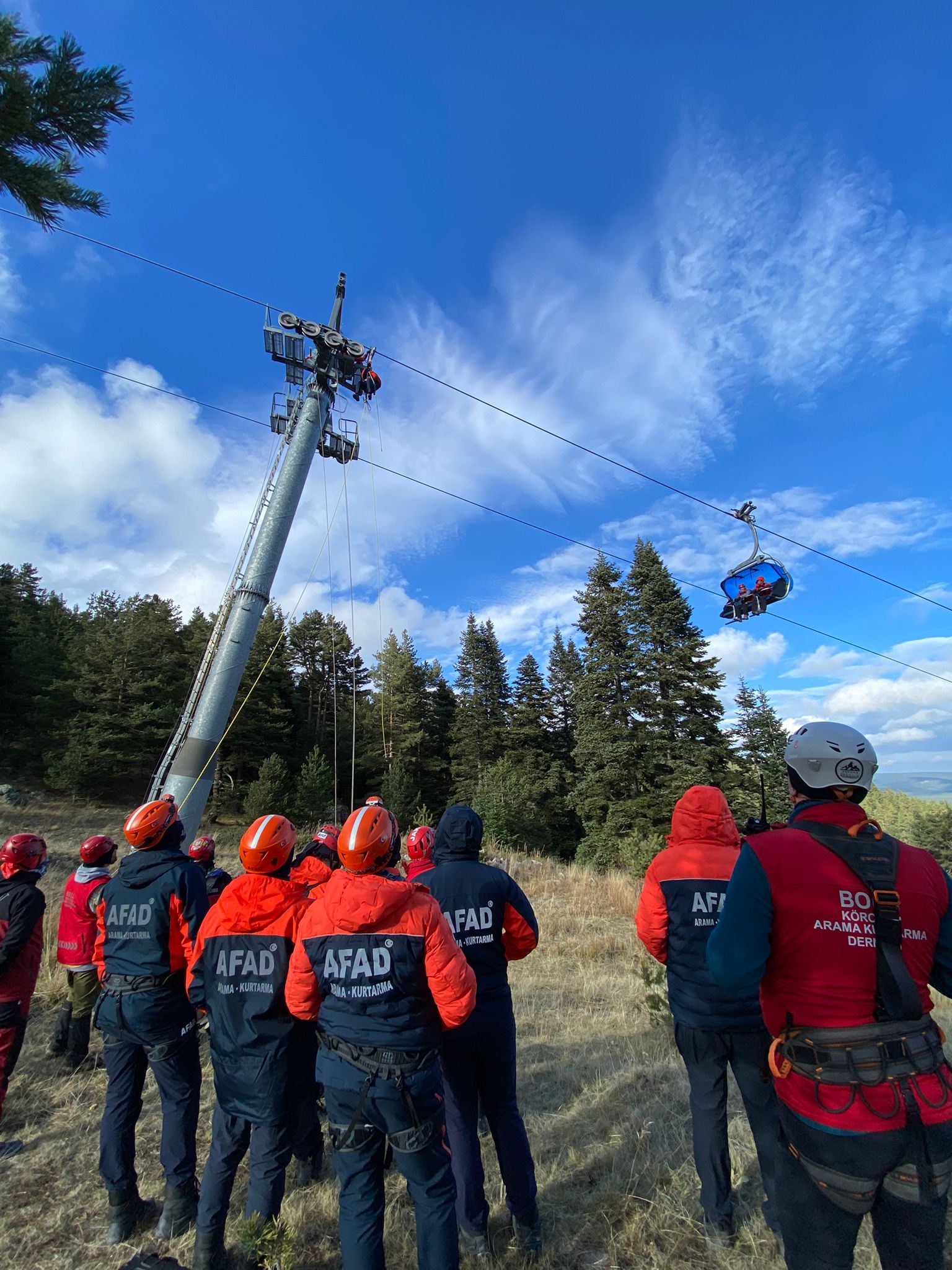
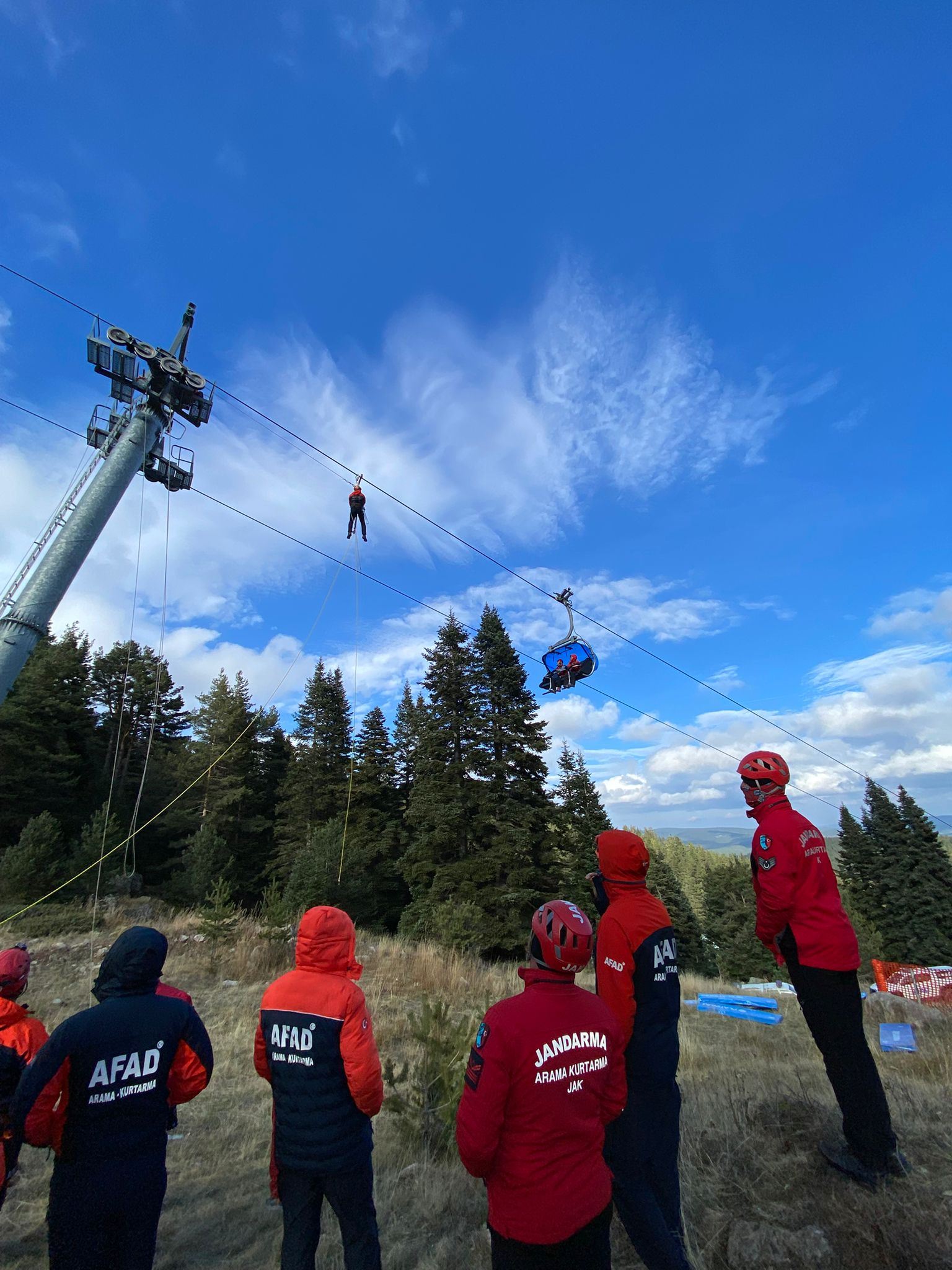
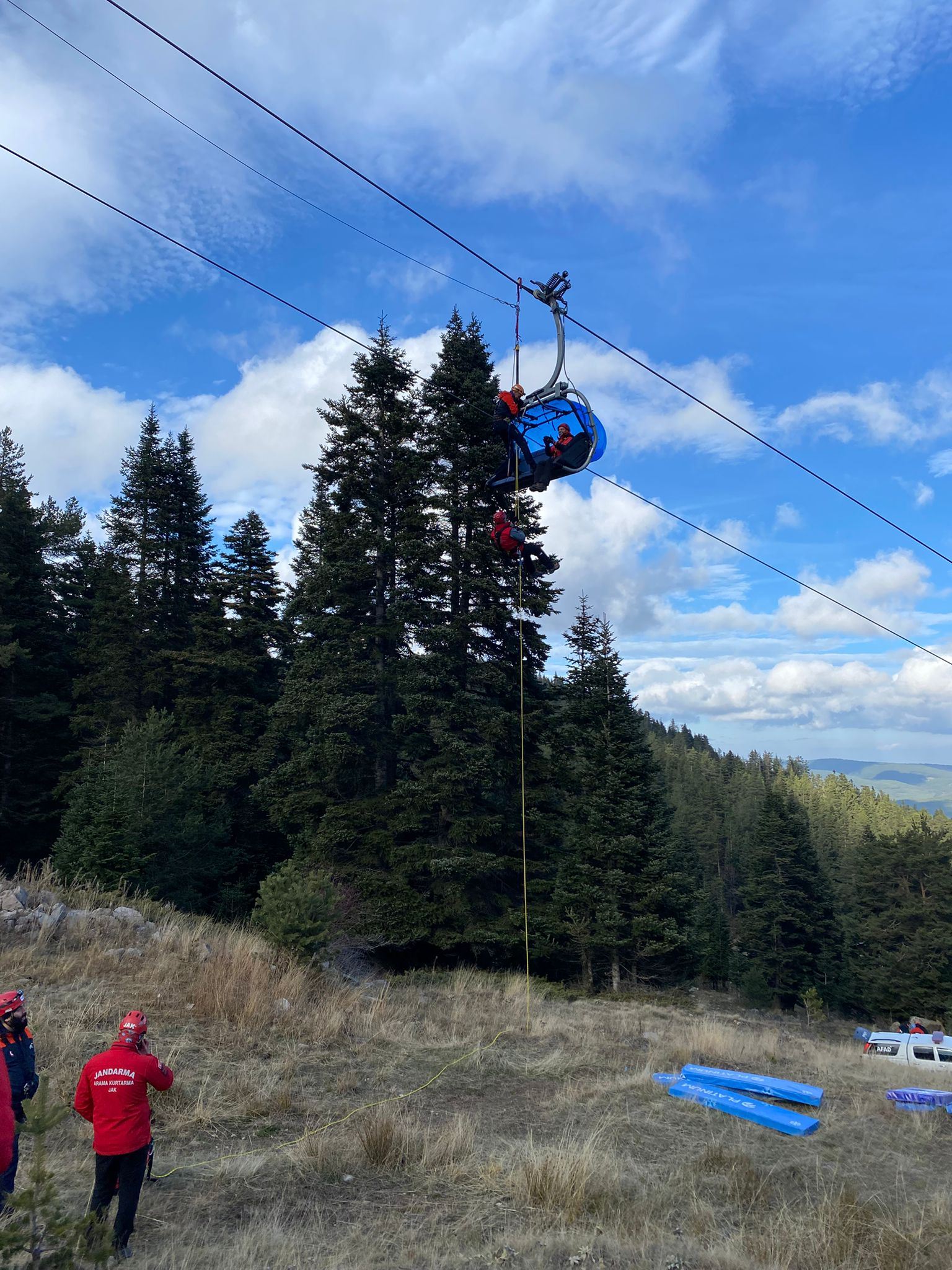
- Lowering from the rope (vertical evacuation). The rescue team reaches the tower or the rope, works out to the carrier and lowers the passengers to the ground under control using a harness and a descent device. It is labour-intensive and slow; it is the last resort.
- Evacuation by helicopter. Applicable only when the weather allows — and in a significant proportion of the situations that require an evacuation, conditions are unfavourable for precisely that reason.
The development of separate evacuation concepts for continuously moving monocable systems dates back to the early 2010s; the new passenger profile brought by urban and tourist lines — older people, children, passengers with reduced mobility — has required those concepts to be rethought.
Case study: a winter evacuation and the lessons drawn
A major breakdown and evacuation operation in the Italian Alps in 2016 went on record as a case in which more than a hundred passengers were evacuated by being lowered from the rope, with dozens of rescuers and snow vehicles coordinated. Conditions were severe: high winds ruled out the use of a helicopter, dusk was approaching, and some sections of the line could not be reached by vehicle or on skis. A large number of organisations, from mountain guides to the fire service, from law enforcement to volunteer medical teams, worked under a single plan, and every passenger was brought down unharmed. The incident showed that the routine gained through drills is decisive at the moment of crisis.
The measures adopted after events of this kind show that the real value of an evacuation lies in what is learnt afterwards: moving to a slow-down rather than a direct stop at the wind limit, improving the line configuration, new lifelines and access routes beneath the line, portable electric floodlights, battery head torches and multiple radio charging units, numbering the undersides of the carriers (so that in the dark it is possible to report without error which cabin is where), and the adoption of devices for independent movement along the rope and for raising a rescuer from the ground.
Team, equipment, drills
The size of the rescue team is determined by the length of the line, the number of carriers, the accessibility of the ground beneath the line and the target evacuation time. To give a sense of scale: in the Alpine regions, operators set up joint rescue networks, first aid stations and helicopter-supported evacuation protocols, with qualified rescuers, rescue snow vehicles, stretcher sledges and defibrillators held in a shared inventory at regional level.
A significant part of the equipment is delivered by the manufacturer together with the installation. Rescue bags, descent devices, harnesses and ropes, a stretcher, heating materials, radios and lighting are inventoried on a pattern similar to the maintenance log and checked regularly.
On the training and drill side, some countries run standardised pre-season training and examination programmes; the training takes place at the installation itself, in an environment where all lift types can be accessed, and is tied to levels of competence recognised by the ropeway authorities. All staff are also required to undergo a personal interview, medical clearance, installation-specific training and refresher training every season. In Switzerland, ropeway expertise and funicular technician qualifications are defined by federal diplomas. In Türkiye, aligning the legislation on technical personnel with field realities — the minimum educational requirements and the recognition of Vocational Qualification Certificates — is among the issues the sector is waiting to see resolved.
Working at height safely
The rescue team and the maintenance team alike do their work on towers, at rope level, and often in poor weather. The hierarchy that applies here does not change: first eliminate the risk; where that is impossible, reduce it with collective protection; and only as a last step fall back on individual protection.
- Isolation and lockout of energy. Before any work begins on the line, it is physically guaranteed that the drive cannot move; no movement command is given without double confirmation by radio.
- Fall protection. A full body harness, a twin-tail lanyard and a fall arrester; anchor points must be defined and marked specifically for the installation.
- Lifelines. Lifelines permanently installed along the line shorten the time needed to move along it, both in maintenance and in evacuation.
- Rescuing the rescuer. Because circulatory problems can develop rapidly in a person left in suspension, the team must have the competence and equipment to bring suspended personnel down quickly. This is written into the work-at-height plan as a separate item.
- Threshold values. Thresholds for stopping work on grounds of wind speed, icing and visibility are set in advance; portable lighting and head torches are mandatory for night work.
All of these topics form part of the installation’s overall safety framework; for the structure of the standards, see the article on cable car safety and the EN standards.
The legal framework in Türkiye
In Türkiye, cableway installations fall under the Cableway Installations Regulation, which was created by harmonisation with Regulation (EU) 2016/424. The obligations on the operating side are defined through TS EN 1709. The Technical Operating Licence file requires not only the technical file and the safety report but also the operating, rescue and dismantling instructions, together with the maintenance and adjustment instructions and the inspection schedule. In other words, the rescue plan is a component of the installation’s licence.
Two recent developments have clarified the timetable. With the amendment made to the Work Equipment Regulation in December 2025, periodic inspection at intervals of no more than one year in accordance with TS EN 1709 became an explicit obligation for cableway installations. From 1 January 2027, these inspections may be performed only by inspection bodies accredited by TÜRKAK under TS EN ISO/IEC 17020.
Against this, there is a compliance gap in the field. Because installations built before July 2009 fall outside the scope of the regulation with the status of “existing installations”, regular supervision and the EN 1709 inspection regime are in practice not applied to them. When one considers that roughly a third of the registered installations date from before 2009, the scale of the problem becomes visible. The approach the sector has proposed at institutional level is that existing installations be inspected by accredited bodies, that the results be turned into a measurable technical reality report, and that decisions be based on that report. For an overview of the variety of installations in Türkiye, see the article on Türkiye’s cable car installations.
Summary
- The maintenance effort exceeds the time the installation spends carrying passengers; preventive maintenance is not a cost item but a precondition of the level of safety.
- The calendar is layered into daily, weekly, monthly, annual and major inspections; the major inspection includes non-destructive testing.
- The anomaly rate peaks in year 20; life-cycle and budget planning are built around that threshold.
- Each critical component has its own standard and its own monitoring method; on the rope, magnetic inspection is indispensable.
- Rescue is not a single method but a graded sequence of steps; lowering from the rope is the last resort.
- Evacuation capability is preserved as much by drills, training and record discipline as by equipment.
For the meanings of the technical terms used in this article, the cable car glossary is a useful reference.